
Decoupling Capacitors: Reducing ESP32 Resets the Right Way
Understand decoupling, bulk capacitance, component placement and voltage-drop testing before using capacitors to address ESP32 resets.
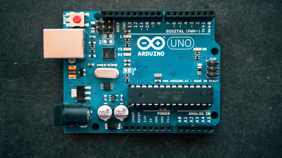
Quick Summary
An ESP32 that resets during WiFi transmission, relay switching or sensor activity may have a supply disturbance, but adding a random capacitor is not a diagnosis. A decoupling capacitor provides a local low-impedance path for transient current and helps control supply noise. Bulk capacitance supports slower load changes. Both complement a suitable supply rather than replacing one.
Capacitance, ESR, voltage rating, dielectric and placement affect performance. Follow the schematic and hardware guidelines for the actual chip or development board. External loads may still need additional support at their point of load.
Separate decoupling from bulk support
A small capacitor such as 0.1 uF is commonly placed very close to an IC supply pin for high-frequency transients. A larger bulk capacitor is placed near a rail entrance or load for slower current changes. These are general principles; the device documentation determines exact values and arrangements.
Traces and vias add inductance, so a distant capacitor becomes less effective at high frequency. Both Espressif and Texas Instruments emphasise short placement near the intended pin or supply entrance.
Identify the real reset source
Possible causes include a weak adapter, high-resistance USB cable, overheating regulator, motor noise, disturbance on EN, a temporary short or a firmware watchdog. A serial reset message can point toward a cause, but measurement is still necessary.
Measure the supply at the board during the event. A handheld meter may miss a short transient, making an oscilloscope more useful when it is available and used safely. Controlled substitution of supply, cable and load also narrows the cause.
Add capacitance safely
Check polarity, voltage rating and discharge state before installing an electrolytic capacitor. Place local decoupling close to the relevant device and bulk capacitance near the load entrance according to guidance. Keep leads short. Very large capacitance can increase inrush current and stress a regulator or switch.
Do not add capacitance to boot, EN or communication signals without understanding timing. A power fix should not accidentally alter control behaviour.
Prove that the change worked
Define a repeatable stress sequence with WiFi activity, relay switching and load startup. Record reset count, minimum observed voltage, regulator temperature and capacitor configuration. Change one factor at a time.
If a better cable solves the issue, report the likely supply-path weakness. If a capacitor reduces resets while voltage still leaves the specified range, the design is not yet validated.
Validation Plan
- Read reset reason and correlate it with load events.
- Measure rails at the controller and point of load.
- Compare before and after using the same stress sequence.
- Check capacitor polarity, rating and component temperature.
Run tests with one controlled change at a time. Preserve configuration, raw measurements and failed runs rather than only successful screenshots. For a final year project, repeatable evidence is stronger than promotional claims. When the available instrument or method cannot prove a statement, report that limitation and define the additional experiment that would be required.
Common Mistakes
- Installing an electrolytic with reversed polarity.
- Using long leads for a local decoupler.
- Masking an undersized regulator with capacitance.
- Changing several parts at once and losing causality.
Move these risks into a checklist or project risk register before demo day. A fault found while architecture and wiring are still flexible is normally less expensive to correct than one discovered after hardware, firmware and report chapters depend on the same assumption.
FAQ
What capacitor value should I add to an ESP32?
There is no universal value. Use the board documentation, load profile and measurement. Espressif gives chip-level guidance, while a finished development board may already implement part of it.
Is every ESP32 reset a brownout?
No. Watchdogs, exceptions, EN, boot pins, heat and firmware can also reset the controller. Use the reset reason and structured tests.
Viva Questions You Should Be Able to Answer
- For Separate decoupling from bulk support, what was design decision 1, which alternative was rejected, and what evidence supports the choice?
- For Identify the real reset source, what was design decision 2, which alternative was rejected, and what evidence supports the choice?
- For Add capacitance safely, what was design decision 3, which alternative was rejected, and what evidence supports the choice?
- For Prove that the change worked, what was design decision 4, which alternative was rejected, and what evidence supports the choice?
A strong answer should cite a requirement, primary datasheet, calculation or result from the student's own tests. For Decoupling Capacitors: Reducing ESP32 Resets the Right Way, avoid saying only that a tutorial used the same method. Explain the selected option, the rejected alternative, test conditions and remaining limitation. Honest boundaries show engineering judgement and make future improvements credible.
Technical References
These references support the general technical principles. Always verify the datasheet for the exact component model, board revision and library version used in the prototype because pins, electrical limits and behaviour can differ.