
Sound Sensor Module
Basic microphone module for noise level and sound-trigger demos.
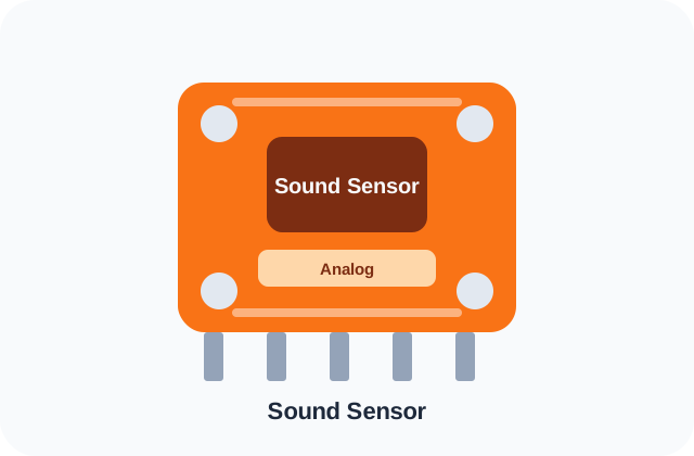
AI Ready Overview
Quick Summary
Sound Sensor is a sound sensor commonly used in FYP and embedded projects. It is best for noise indicator and clap trigger, with wiring and testing planned around Arduino, ESP32.
Difficulty
Beginner
Time Required
1-3 days for basic wiring and sample code; 1 week if used inside a complete FYP prototype
Cost
RM3-RM12 module range in Malaysia; full project cost depends on scope.
Components
Sound Sensor, Arduino, ESP32
Overview
What is Sound Sensor?
Sound sensor modules detect sound intensity using a microphone and amplifier. They are useful for classroom noise indicators and simple sound-triggered alerts.
Engineering Reference
Quick Specs
| Operating Voltage | 3.3V / 5V |
|---|---|
| Interface | Analog, Digital |
| Difficulty | Beginner |
| Typical Malaysia Price | RM3-RM12 |
| Best For | Noise indicator, Clap trigger |
Real Usage Notes
Suitable / Not Suitable
Suitable for
- ✓ Noise indicator
- ✓ Clap trigger
- ✓ Classroom comfort demo
Not suitable for
- ✕ Calibrated decibel meter
- ✕ Voice recognition
- ✕ Audio recording quality
Build Planning
Difficulty
Sound Sensor is rated Beginner. Plan around 1-3 days for basic wiring and sample code; 1 week if used inside a complete fyp prototypedepending on wiring, libraries, calibration, dashboard/app integration and testing evidence.
Build Planning
Time Required
1-3 days for basic wiring and sample code; 1 week if used inside a complete FYP prototype
Malaysia Price Guidance
Cost
Typical module price range: RM3-RM12. This is component guidance only; a complete FYP cost depends on controller, sensors, casing, display, app/dashboard, documentation and timeline.
Connections
Connection overview
Power
Use only a supply supported by the exact board or module variant. Common listings for this part mention 3.3V or 5V.
Ground
Connect a common ground between the controller, module and any external supply.
Primary interface
Plan for Analog / Digital; confirm the exact terminal names in the manufacturer documentation.
Variant-specific connections
Connector names and optional pins can differ between breakout-board revisions.
Platform Notes
Wiring Guides
Sound Sensor with Arduino / ESP32
This is a planning overview, not a board-specific pin map. Confirm the exact module revision, supply limits and Analog / Digital terminals in its datasheet before wiring. Use suitable level shifting when logic voltages differ.
| Power | Confirm against the exact board; listed variants commonly use 3.3V / 5V |
|---|---|
| Ground | Common ground with the controller |
| Interface | Analog, Digital (exact pins vary by module) |
Fix Common Problems
Troubleshooting
Troubleshooting
Common Mistakes
FYP Ideas Using Sound Sensor
Related Projects
Compare Options
Alternative Components
Student Questions
FAQ
Is Sound Sensor good for FYP projects?
Yes, Sound Sensor is suitable for FYP work when the project matches its limits: Noise indicator and Clap trigger.
What is the most common Sound Sensor mistake?
Claiming accurate dB without calibration