
ESP32 Strapping Pins Explained: GPIO0, GPIO2, GPIO5, GPIO12 and GPIO15
Learn what ESP32 strapping pins do, why wrong pull-up or pull-down wiring can break boot, and how to avoid upload problems in FYP projects.
Rectronx
2026-07-28
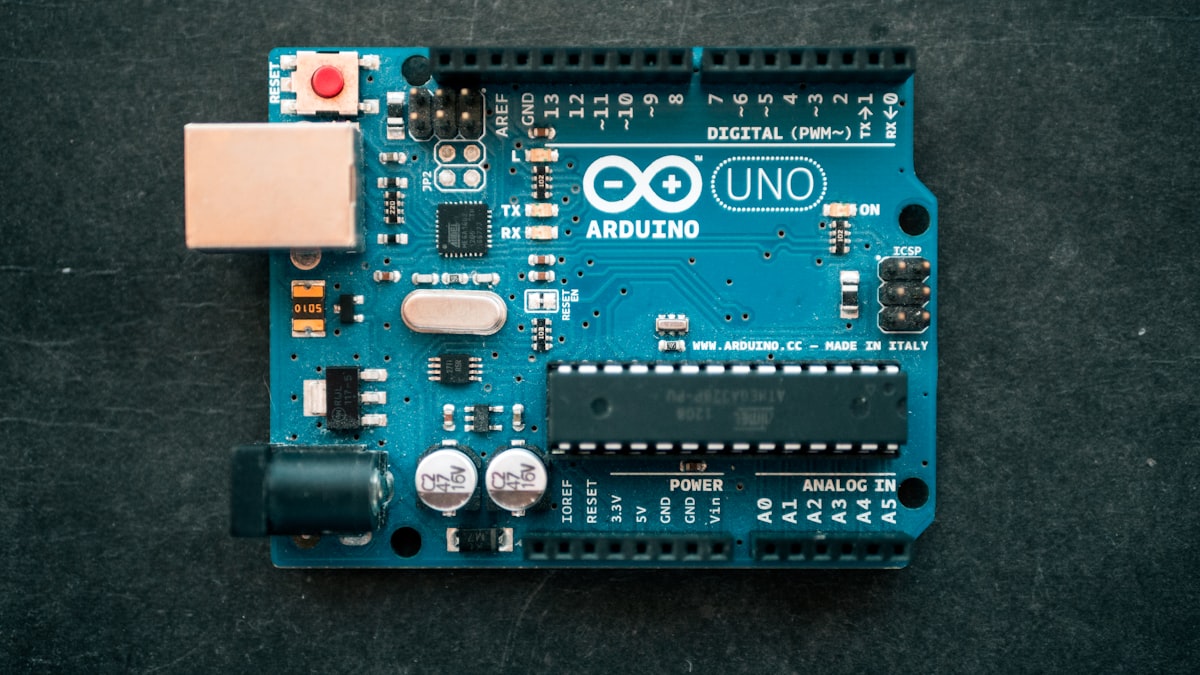
ESP32 strapping pins are GPIO pins that affect the chip during reset and boot. They can still be used in projects, but they need respect. If your external circuit pulls one of these pins to the wrong level at startup, the ESP32 may fail to boot or fail to enter upload mode.
The main ESP32 strapping pins are GPIO0, GPIO2, GPIO5, GPIO12 and GPIO15. You can inspect them quickly in the ESP32 Pinout Tool by using the Boot filter.
Why Strapping Pins Matter
When ESP32 resets, it samples certain pins to decide startup configuration. That is useful inside the chip, but it creates a practical problem for students: a sensor, button, relay board or module can accidentally force a pin level during boot.
The result may look confusing:
- Code uploads only sometimes.
- Board needs the BOOT button to be held.
- Serial monitor shows boot messages but the sketch does not run.
- Project works on USB, then fails when powered from battery.
Strapping Pin Table
| Pin | Why to be careful |
|---|---|
| GPIO0 | Often involved in bootloader/upload mode. |
| GPIO2 | Strapping pin and onboard LED on some boards. |
| GPIO5 | Often used as SPI CS after boot, but still sampled at startup. |
| GPIO12 | Strapping pin; external pull level can affect boot configuration. |
| GPIO15 | Strapping pin and also related to JTAG on ESP32. |
For beginner FYP demos, avoid these pins for circuits that have uncertain startup states.
Common Mistake: Button On GPIO0
GPIO0 is often tied to boot mode behavior. If you add a button, sensor output or external module that pulls GPIO0 low at the wrong time, the ESP32 may enter bootloader mode instead of running your project.
Use a safer pin like GPIO16, GPIO17, GPIO18, GPIO19, GPIO21, GPIO22, GPIO23, GPIO32 or GPIO33 for ordinary buttons and signals when possible.
Common Mistake: Relay On A Boot Pin
Relay modules can have pull-up or pull-down behavior on their input pins. If a relay input is connected to a strapping pin, it may affect boot or switch unexpectedly during reset.
For relay outputs, choose a safer general-purpose GPIO and use a proper relay module. Never power a relay coil directly from an ESP32 GPIO.
How To Test Before Demo
After wiring your project:
- Power the ESP32 from USB and confirm it boots.
- Press reset several times.
- Upload code several times.
- Power from your final adapter or battery.
- Reset again and observe whether boot is stable.
If the project only works after you unplug modules or hold the BOOT button, check whether you used a strapping pin.
Final Advice
Strapping pins are not forbidden. They are riskier. For student projects, use them only when needed and document the reason. For quick checking, open the ESP32 Pinout Tool, select Boot, and keep risky pins away from uncertain external circuits.